- Battery Manufacturing Equipment
- Battery Laboratory Assembly Equipment
- Battery Pack Assembly Equipment
- Sodium Ion Battery Manufacturing Equipment
- Solid State Battery Assembly Line
- Dry Electrode Assembly Equipment
- Supercapacitor Assembly Equipment
- Perovskite Solar Cell Lab Equipment
- Li ion Battery Materials
- Ni / Al / Cu Metal Foam
- Customized Electrode
- Cathode Active Materials
- Anode Active Materials
- Coin Cell Parts
- Lithium Chip
- Cylindrical Cell Parts
- Battery Current Collectors
- Battery Conductive Materials
- Electrolyte
- Battery Binder
- Separator and Tape
- Aluminum Laminate Film
- Nickel Strip/Foil
- Battery Tabs
- Graphene Materials
- Cu / Al / Ni / Stainless steel Foil
- Battery Laboratory Equipment
- Li ion Battery Tester
- Battery Safety Tester
- Battery Material Tester
- Film Coating Machine
- Rolling Press Machine
- Electrode Mixer
- Coin Cell Crimping Machine
- Coin Cell Electrode Disc Punching
- Pouch Cell Sealing Machine
- Pouch Cell Stacking Machine
- Pouch Cell Forming Machine
- Pouch Cell Ultrasonic Welder
- Pouch Cell Electrode Die Cutter
- Cylinder Cell Sealing Machine
- Cylinder Cell Grooving Machine
- Electrode Slitting Machine
- Cylinder Cell Winding Machine
- Cylinder Cell Spot Welding Machine
- Electrolyte Filling
- Type Test Cell
- Other Battery Making Machine
- NMP Solvent Treatment System
- Vacuum Glove Box
- Lab Furnaces
- Ball Mill
- Hydraulic Press
- Laboratory Equipment
5V100A 8 Channel Negative Pressure Formation Machine For Prismatic Cell Assembly
Model Number:
TMAX-FY8CH-5V100ACompliance:
CE certificateWarranty:
Two Year Limited Warranty With Lifetime SupportPayment:
T/T, Credit Card, Paypal, LC, Western UnionDelivery Time:
3 Days
Wechat:13506084915
1. Equipment Overview
Equipment Function:
The equipment is primarily used for the formation process of prismatic lithium-ion batteries under negative pressure.
This equipment includes:
2 sets of power cabinets (5V100A, total 8 channels)
1 set of pin bed fixture group (8 channels/set)
1 set of negative pressure vacuum system
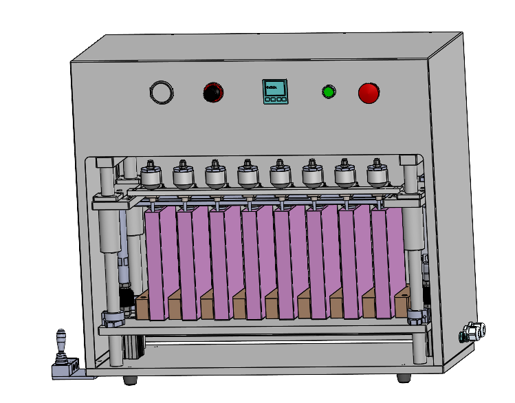
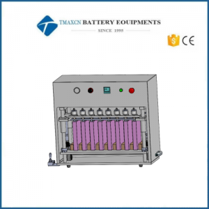
Equipment Appearance Diagram
2. Process Flow
l Manually place the battery into the fixture group
l Start the pin bed
l Start the negative pressure process and charge formation
l Formation complete
l Manually open the pin bed fixture
l Manually remove the battery
3. Technical Parameters
l Applicable Prismatic Cell Models: 50160116, 20100140
l Formation Channels: 8 channels
l Achievable Vacuum Degree: 0 to -95kPa
l Probe Plate Assembly Design: Modular design for quick extraction and replacement
l Cabinet Features: Equipped with smoke detectors and other monitoring systems, 24-hour monitoring, proactive safety measures
l Tester Parameters:
|
Item |
Parameters |
|
Communication Method |
TCP/IP (Network Port) |
|
Channel Control Mode |
Single Channel Independent Control |
|
Charging Energy Efficiency |
80% |
|
Charging Voltage |
0~5V |
|
Discharging Voltage |
5~1.5V (Test line < 2 meters) |
|
Charging Current |
0.2A~100A |
|
Discharge Feedback Efficiency |
75%, standard sine wave feedback energy, high efficiency, excellent energy-saving effect |
|
Discharging Current |
0.5A~100A |
|
Voltage Accuracy |
±(0.05%RD + 0.05%FS) |
|
Current Accuracy |
±(0.05%RD + 0.05%FS) |
|
Voltage Resolution |
0.1mV |
|
Current Resolution |
0.1mA |
|
Output Power Stability |
±(0.05%RD + 0.05%FS) |
|
Sampling Time |
Single channel sampling frequency ≥ 10ms |
|
Recording Time |
100ms~65535s |
|
Charging Modes |
Constant Current Charging (CC), Constant Voltage Charging (CV) (requires CC+CV mode), Constant Current and Constant Voltage Charging (CCCV), Constant Power Charging (CPC) |
|
Charging Cut-off Conditions |
Voltage, current, time, capacity, temperature (optional, customizable) |
|
Discharging Modes |
Constant Current Discharging (CD), Constant Power Discharging (CPD), Constant Current and Constant Voltage Discharging (DCCV) (optional, customizable) |
|
Discharging Cut-off Conditions |
Voltage, current, time, capacity, temperature (optional, customizable) |
|
Sampling Method |
Voltage and current use a special four-wire connection |
|
Single Cycle Step Count |
Single cycle step count |
|
Circuit Structure |
Modular design for easy replacement and maintenance |
|
Software and Hardware Protection |
Reverse connection protection, overvoltage protection, overcurrent protection, overtemperature protection, undervoltage protection, short circuit protection |
|
Main System Functions |
1. Software supports various continuation methods such as manual pause continuation, software shutdown continuation, power outage continuation, equipment communication interruption continuation, and abnormal stop continuation. 2. Supports barcode scanning for one-dimensional and two-dimensional codes, with sequential scanning, channel jumping scanning, and tray scanning. 3. Detailed local test data storage, allowing for real-time viewing of current and historical test data for each channel, presented in both data and curve formats, supporting single or batch export of Excel reports, with automatic data export upon test completion if required. 4. Supports capacity sorting, grading batteries, and indicating with LED lights. 5. Supports end-of-test pass/fail judgment based on specified cycle capacity, voltage, time, etc. 6. Supports various step protections and global voltage, current, temperature (optional, customizable) abnormal protection, with abnormal alarms. 7. Supports unit conversion. 8. Supports customizable MES development (not standard). 9. Offline protection for software and hardware. 10. Real-time voltage collection filtering, pre-test battery pressure inspection, and post-test formation voltage screening. 11. Provides lifetime free software upgrades. |
|
System Protection |
Global protection parameters (including battery reverse connection protection, undervoltage protection, overvoltage protection, overcurrent protection, overtemperature protection), CC charging protection parameters (voltage trend abnormal protection, charging current fluctuation abnormal protection, voltage fluctuation abnormal protection, charging voltage time setting, charging voltage rise speed abnormal protection), CV charging protection parameters (including current trend abnormal protection, charging current fluctuation abnormal protection, voltage fluctuation abnormal protection), CC discharging protection parameters (including voltage trend abnormal protection, discharging current fluctuation abnormal protection, voltage fluctuation abnormal protection, discharging voltage drop speed abnormal protection), Idle protection parameters (including voltage abnormal jump protection). When each protection reaches user-set parameters, the equipment will automatically stop channel operation, issue an alarm, and record the event for tracking. |
|
Data Monitoring and Viewing |
During system operation, the software main window displays real-time data for each channel, including current, voltage, charge/discharge capacity, operation step process, and current operation step name. The software also allows for viewing current and historical data at any time and exporting to Excel format manually or automatically. |
|
Communication Method |
Equipment and middle machine communicate via CAN interface, while middle machine and upper machine use LAN port TCP/IP protocol communication, ensuring stable and real-time long-distance data collection. All communication ports are isolated and designed with lightning protection. |
4. Protection Functions
4.1. Data anomaly recovery;
4.2. Software overvoltage, undervoltage, overcurrent, undercurrent, overcapacity protection;
4.3. Voltage and current protection values can be set, with prompts and records after protection;
4.4. Emergency stop button setup, with automatic fixture release upon emergency stop;
4.5. Equipped with a smoke alarm; machine stops running and alarms when smoke is detected;
4.6. After equipment alarm shutdown, the process can continue from the interruption point without restarting the process;
4.7. If the communication between the lower machine and the upper machine is interrupted, it can continue working according to the original process after communication resumes;
4.8. When an abnormal power outage occurs, the current process step can continue;
4.9. In case of time communication interruption or PC failure, the equipment will automatically enter a waiting state and resume the current process after communication quickly resets.
5. Main Component Configuration
5.1. Fixture Structure Diagram
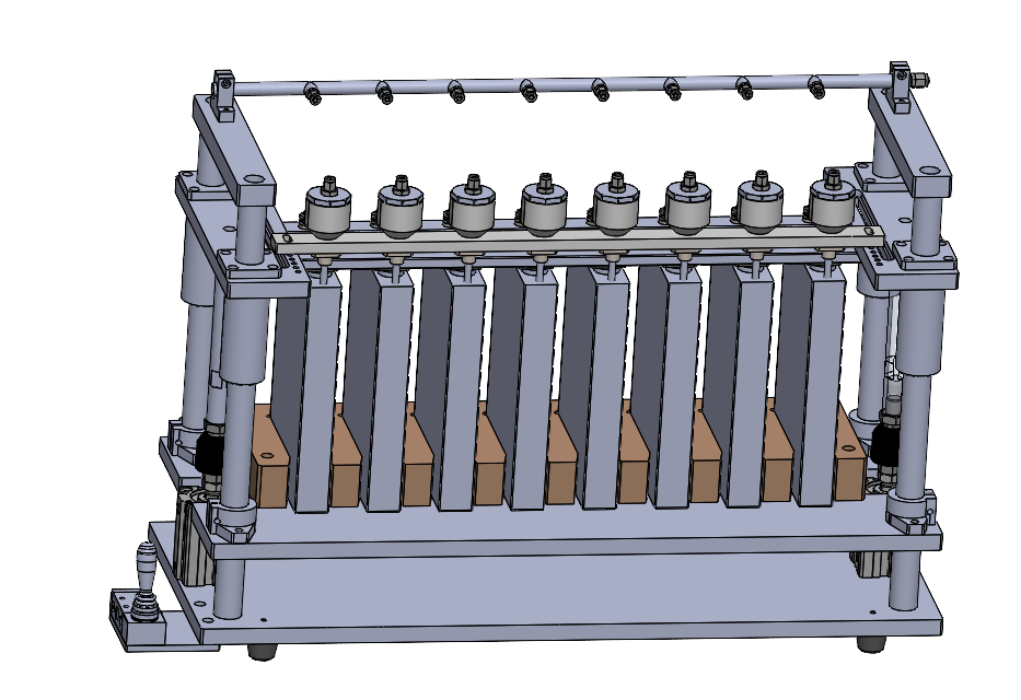
5.2. High-Current Probe Structure Diagram
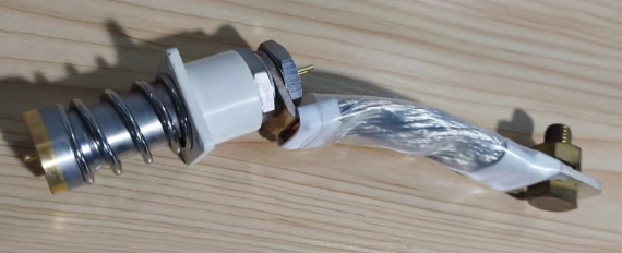
5.3. Negative Pressure Suction Cup Structure Diagram
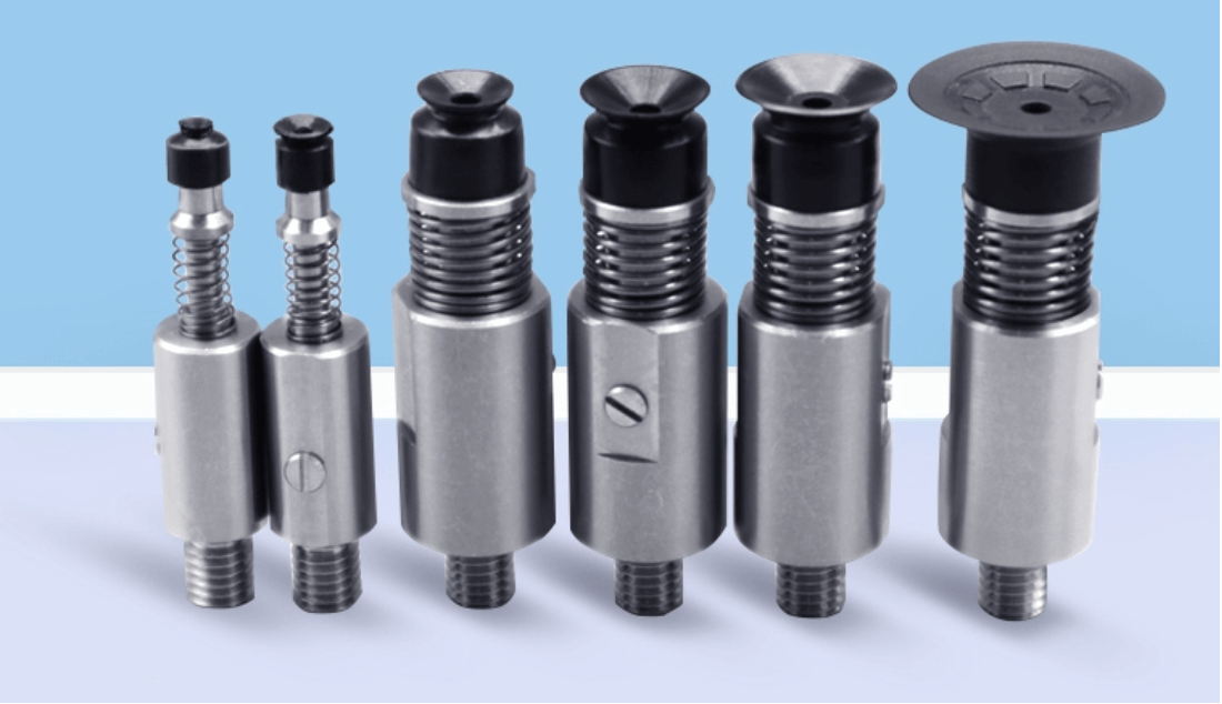
5.4. Negative Pressure Cup (the overall structure uses specially treated materials resistant to corrosion and high temperature, with flexible PTFE corrosion-resistant material for negative pressure pipelines)

6. Main Spare Parts Brands
|
No. |
Name |
Brand |
|
1 |
Digital Vacuum Pressure Gauge |
SMC or equivalent |
|
2 |
Pneumatic Components |
Airtac/SMC or equivalent |
|
3 |
Test Probe |
Custom (Copper Plated Gold) |
|
4 |
Negative Pressure Suction Cup |
Custom |
|
5 |
Power Cabinet |
Custom |
7. List of Random Accessories
|
No. |
Name |
Specifications |
Quantity |
Remarks |
|
1 |
Test Probe |
Custom |
1 pc |
|
|
2 |
Negative Pressure Nozzle |
Custom |
1 pc |
|
8. Installation Environment Requirements
8.1. Power Supply: AC380V, 50Hz, voltage fluctuation range: +10%~-10%; total equipment power about 5KW.
8.2. Compressed Air: 0.6~0.8Mpa; air pressure fluctuation ±1% (clean air after water removal, oil removal, filtration, and pressure stabilization).
8.3. Vacuum Source: -98KPa.
8.4. Dry Nitrogen Source: 0.1~0.3Mpa.
8.5. Equipment Specifications:
1). Equipment weight: approximately 90kg.
2). Dimensions: approximately L0.85m x W0.4m x H0.7m.
3). Appearance color: light gray or as specified by the customer.
8.6. Environmental Requirements:
1). Ambient temperature: 0~45℃.
2). Relative humidity: 30%~75%RCH, ensuring dry and ventilated site air without acid and alkali corrosion.
3). Grounding: protective grounding.



 ru
ru

 cindy@tmaxcn.com
 David@battery-equipments.com
 Wechat:13506084915