- Battery Manufacturing Equipment
- Battery Laboratory Assembly Equipment
- Battery Pack Assembly Equipment
- Sodium Ion Battery Manufacturing Equipment
- Solid State Battery Assembly Line
- Dry Electrode Assembly Equipment
- Supercapacitor Assembly Equipment
- Perovskite Solar Cell Lab Equipment
- Li ion Battery Materials
- Ni / Al / Cu Metal Foam
- Customized Electrode
- Cathode Active Materials
- Anode Active Materials
- Coin Cell Parts
- Lithium Chip
- Cylindrical Cell Parts
- Battery Current Collectors
- Battery Conductive Materials
- Electrolyte
- Battery Binder
- Separator and Tape
- Aluminum Laminate Film
- Nickel Strip/Foil
- Battery Tabs
- Graphene Materials
- Cu / Al / Ni / Stainless steel Foil
- Battery Laboratory Equipment
- Li ion Battery Tester
- Battery Safety Tester
- Battery Material Tester
- Film Coating Machine
- Rolling Press Machine
- Electrode Mixer
- Coin Cell Crimping Machine
- Coin Cell Electrode Disc Punching
- Pouch Cell Sealing Machine
- Pouch Cell Stacking Machine
- Pouch Cell Forming Machine
- Pouch Cell Ultrasonic Welder
- Pouch Cell Electrode Die Cutter
- Cylinder Cell Sealing Machine
- Cylinder Cell Grooving Machine
- Electrode Slitting Machine
- Cylinder Cell Winding Machine
- Cylinder Cell Spot Welding Machine
- Electrolyte Filling
- Type Test Cell
- Other Battery Making Machine
- NMP Solvent Treatment System
- Vacuum Glove Box
- Lab Furnaces
- Ball Mill
- Hydraulic Press
- Laboratory Equipment
16 Channel Battery Capacity Tester Aging Machine For Supercapacitors
Model Number:
TMAX-5V100A16CCompliance:
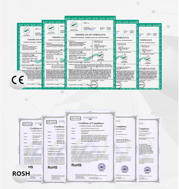
CE certificateWarranty:
Two Year Limited Warranty With Lifetime SupportPayment:
T/T, Credit Card, Paypal, LC, Western UnionDelivery Time:
3 Days
Wechat:13506084915
16 Channel Battery Capacity Tester Aging Machine For Supercapacitors
Introduction
The device is mainly used for the primary charging of super capacitor. The whole machine is composed of a formation unit and a set of pressing machine, in which the formation unit has 16 channels and 1 layer, each layer has a set of press corresponding to it, and each formation unit is composed of 16 channels of 5V 100A. The circuit connection between the battery and the equipment is realized by the probe. The probe is installed on the pressing machine, and the whole tray capacitance is put into the equipment manually. The needle bed mechanism of the device presses the probe and the positive and negative poles of the capacitance through appropriate pressure, so as to realize the fast and reliable connection between the needle bed and the capacitance.
2.1 Requirements and objectives of scheme design
At present, customers need to test the capacity of cylindrical capacitor, and the applicable battery specifications (as shown in the table below): the detailed dimensions shall be subject to the battery outline dimension drawing.

2.2 Main functions of the system
The main functions of the press are as follows:
1) Provide four electrode probe for battery test;
2) Press the electrode to ensure the reliable connection between the electrode and the chemical forming machine;
3) Provide capacitor tray docking and pressing machine and positioning mechanism.
3. Overall scheme design
3.1 overall system composition:
1) 16 channel needle bed

3.2 scheme design of Mechanical Department
3.2.1 pallets

An annular convex plate is set at the bottom of a single cell, which can store part of the leaked electrolyte. The upper and lower cooling channels are set at the cross point of the reinforcing ribs, so that the tray has good heat dissipation performance. At the same time, the transverse frame is widened nearly twice to increase the strength of the tray, which can effectively prevent the concave deformation of the tray.
3.2.2 Heat flow analysis

Heat dissipation mode:
Fan cooling mechanism is designed at the top of each press unit, with air inlet at the top and air outlet at the bottom and around the tray to ensure uniform temperature in the unit.
Exhaust air volume: 500m3 / h
3.2.3 Test probe and thermistor
(refer to drawing)

3.2.4 Probe module
(refer to drawing)

A single probe module consists of 16 channels and one unit.
3.2.5 upper and lower plate flow (illustration legend, for reference only.)


If the tray is not in place, the needle bed will not be pressed down. (illustration, for reference only.)
3.3 calibration tooling system:
1. Composition of calibration tooling system
The structure of tooling system is shown in the figure below: it is composed of debugging tray, operating computer and measuring multimeter. The special measurement and control software is installed on the computer to control the debugging tray, complete the automatic switching of current and voltage measurement channels, and read the measured value of the multimeter; the specified high-precision 6-1 / tray 20 multimeter (34401A) is used for the multimeter; the debugging device can complete the current and voltage measurement or current calibration of a tray (16 channel battery) under the control of the computer.

2. Test process description
1) Connect the power supply of equipment and debugging device;
2) Put the debugging tray into the needle bed;
3) Connect the cable and communication line of debugging device (including computer, multimeter and debugging tray);
4) Start the special software of the computer calibration tooling system, set the parameters and start the test. After start-up, the computer will automatically control the power supply equipment to enter the charging / discharging state according to the set current value. At the same time, it will control the test device to switch channels, calibrate or measure the set channels. After the test is completed, the data will be automatically summarized into excel table.


 ru
ru


 cindy@tmaxcn.com
 David@battery-equipments.com
 Wechat:13506084915