- Battery Manufacturing Equipment
- Battery Laboratory Assembly Equipment
- Battery Pack Assembly Equipment
- Sodium Ion Battery Manufacturing Equipment
- Solid State Battery Assembly Line
- Dry Electrode Assembly Equipment
- Supercapacitor Assembly Equipment
- Perovskite Solar Cell Lab Equipment
- Li ion Battery Materials
- Ni / Al / Cu Metal Foam
- Customized Electrode
- Cathode Active Materials
- Anode Active Materials
- Coin Cell Parts
- Lithium Chip
- Cylindrical Cell Parts
- Battery Current Collectors
- Battery Conductive Materials
- Electrolyte
- Battery Binder
- Separator and Tape
- Aluminum Laminate Film
- Nickel Strip/Foil
- Battery Tabs
- Graphene Materials
- Cu / Al / Ni / Stainless steel Foil
- Battery Laboratory Equipment
- Li ion Battery Tester
- Battery Safety Tester
- Battery Material Tester
- Film Coating Machine
- Rolling Press Machine
- Electrode Mixer
- Coin Cell Crimping Machine
- Coin Cell Electrode Disc Punching
- Pouch Cell Sealing Machine
- Pouch Cell Stacking Machine
- Pouch Cell Forming Machine
- Pouch Cell Ultrasonic Welder
- Pouch Cell Electrode Die Cutter
- Cylinder Cell Sealing Machine
- Cylinder Cell Grooving Machine
- Electrode Slitting Machine
- Cylinder Cell Winding Machine
- Cylinder Cell Spot Welding Machine
- Electrolyte Filling
- Type Test Cell
- Other Battery Making Machine
- NMP Solvent Treatment System
- Vacuum Glove Box
- Lab Furnaces
- Ball Mill
- Hydraulic Press
- Laboratory Equipment
Slurry Iron Removing Filter and Conveying Machine
Model Number:
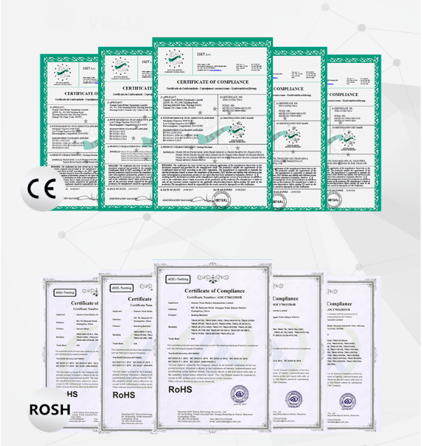
TMAX-TG60Compliance:
CE compliantWarranty:
Two Year Limited Warranty With Lifetime SupportPayment:
T/T, Credit Card, Paypal, LC, Western UnionDelivery Time:
3 Days
Wechat:13506084915
Slurry Iron Removing Filter and Conveying Machine
Process diagram and description
1#Scheme:

2#Scheme:

1. The slurry stored in the turnover tank is transported to the "coating machine hopper" through the "diaphragm pump, pipeline, filtered, and iron removed".
2. The parts are connected by quick-fitting parts and fixed and supported by pallets, and transferred through the control system and pipelines.
3. Special attention: The "piping valve and liquid level control" between the system and the coating machine hopper/liquid storage tank must be installed and controlled by the "demand party and its coating manufacturer", which is different from the "demand party's The coating workshop site is closely related to the coating machine purchased".
Equipment composition and capabilities
|
No. |
Name |
Model |
Unit |
Quantity |
Note |
|
1 |
Pneumatic double diaphragm pump |
3/4"--Skaly or Graco |
Set |
1 |
With standard ISO quick connection |
|
2 |
Filter element |
Ф76*200 |
Set |
1 |
100-250 mesh |
|
3 |
Magnetic bar |
Ф25*156 |
Pcs |
3 |
10000GS/pcs |
|
4 |
Pressure gauge |
ф60--1Mpa |
Pcs |
1 |
SUS304 |
|
5 |
Applicator |
3 groups of applicator |
Pcs |
1 |
Applicator material: PTFE (Teflon) Spring material: stainless steel made in Japan |
|
6 |
Connecting pipe valves, pipe fittings |
Ф25 |
Set |
1 |
SUS304 |
|
7 |
Stainless steel tray |
Non-standard (length * width * height) mm |
Pcs |
1 |
SUS304 |
|
8 |
System control box |
Liquid level, pressure, alarm, control |
Set |
1 |
SUS304 |
|
9 |
Conveying capacity |
Working capacity: 20L/Min |
|
|
|
Other instructions and points of attention
1. "Shaft seal, scraper, filter element" in this system are consumables;
2. This system is only suitable for "single variety slurry and continuous production mode"; taboo "frequent variety change and intermittent production mode";
2-1. If you change the "material system", please clean up (pipeline, magnetic filter) and replace all key parts (filter element/screen) in advance, and it is better to replace the pipeline.
2-2. During normal use, ensure that there is "sufficient slurry" remaining in the pipeline to prevent air moisture from entering, so as to prevent the slurry from "solidifying"!

2-3. Dimensions 500mm*1000mm*900mm (length, width and height)


 ru
ru


 cindy@tmaxcn.com
 David@battery-equipments.com
 Wechat:13506084915